 Patented by
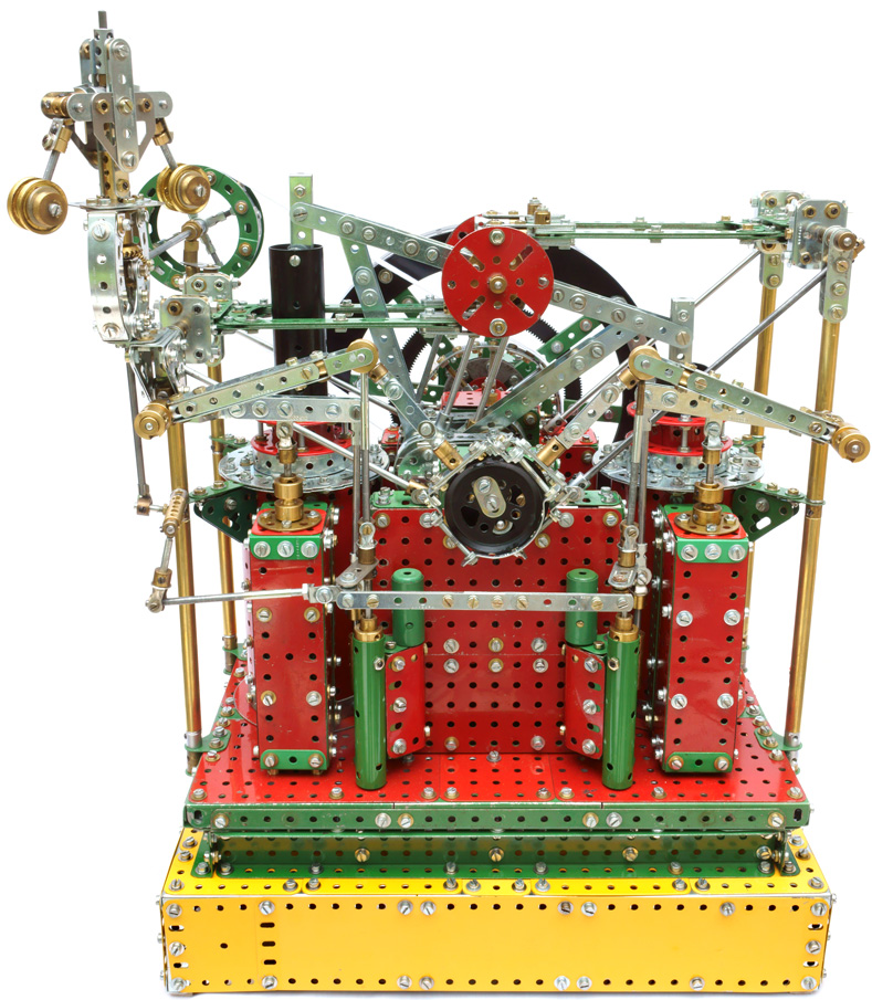
Norman Wheeler in 1867, this complex design was far more compact than
conventional engines of similar capacity. The tumbling beam arrangement
enabled width to be saved by connecting two cylinders to a single crank,
and much height to be saved by having the cylinders positioned alongside
the crankshaft and by using unusual, tubular pistons without crosshead
guides. The connecting rods to the top corners
of the tumbling beam (which do not have a true vertical motion) are
connected to swivel bearings set low inside the hollow pistons. External crosshead guides are unnecessary because the swivel bearings
are
inside the cylinders and no significant lateral forces bear on the
pistons.
Patented by
Norman Wheeler in 1867, this complex design was far more compact than
conventional engines of similar capacity. The tumbling beam arrangement
enabled width to be saved by connecting two cylinders to a single crank,
and much height to be saved by having the cylinders positioned alongside
the crankshaft and by using unusual, tubular pistons without crosshead
guides. The connecting rods to the top corners
of the tumbling beam (which do not have a true vertical motion) are
connected to swivel bearings set low inside the hollow pistons. External crosshead guides are unnecessary because the swivel bearings
are
inside the cylinders and no significant lateral forces bear on the
pistons.
The two, double-acting cylinders are phased a half-stroke apart. A heavy balance weight in the flywheel rim is necessary to counterbalance the tumbling beam and pistons.
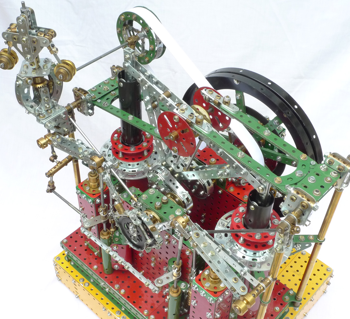
The engine incorporates another Wheeler patent - hydraulic valve actuators. With these, there is no direct mechanical link between the crankshaft and the intake and exhaust valves. Instead, the master cylinder of each valve actuator is driven by a an eccentric on the engine crankshaft, and a 4-position, stepped motion is transmitted hydraulically to the inlet/exhaust slide valve of the driving (steam) cylinder via a link to the actuator's slave cylinder. Valve timing is controlled by a conventional centrifugal governor, itself linked to the hydraulic valve actuators. The link from the governor adjusts timing by rotating the (horizontally-linked) master cylinder pistons of the hydraulic actuators. On the model, the stepped, reversing motion of the slide valves is simulated mechanically by a quad-cam mechanism (which keeps in precise step with the crankshaft) concealed in the plinth.


![]() Although very
compact, the design had many drawbacks. Its complexity would have made
it expensive to manufacture and require more maintenance, and with its
non-compound cylinders and slide valves, it would have been less
thermo-dynamically efficient than conventional engines.
Although very
compact, the design had many drawbacks. Its complexity would have made
it expensive to manufacture and require more maintenance, and with its
non-compound cylinders and slide valves, it would have been less
thermo-dynamically efficient than conventional engines.
To see the model in action, click picture on right. ►
Like many patent designs, the engine never went into production. The is no surviving prototype (if one were ever constructed) and the model is built from the drawings published in a contemporary edition of "The Engineer" journal. The intended scale is not indicated; the model has a similar (overall) bore and (4.3") stroke to my 2-cylinder Diamond Rope Works Engine, yet it is half that model's height, illustrating the extreme compactness of the Tumbling-Beam engine.